Description
- Number of Compartments: RGB MOD
- Bluetooth range: 00
- Occasion: Others
- Portable: Yes
- Platform: Other
- High-concerned chemical: None
- Cable features: Retractable
- Number of Pins: 4
- Harness Feature: Others
- Sensor Technology: Others
- Electric: No
- Accessories Type: Accessory Kits
- Control Method: Touch
- With USB: No
- Controls Type: Others
- Enclosure material: Others
- Mfr part number: MOD260701
- Model Number: RGB-MOD-201
- Compatible Nintendo Model: Nintendo64
- Compatible Brand/Model: Nintendo
- Origin: Mainland China
Must Read Before Buying
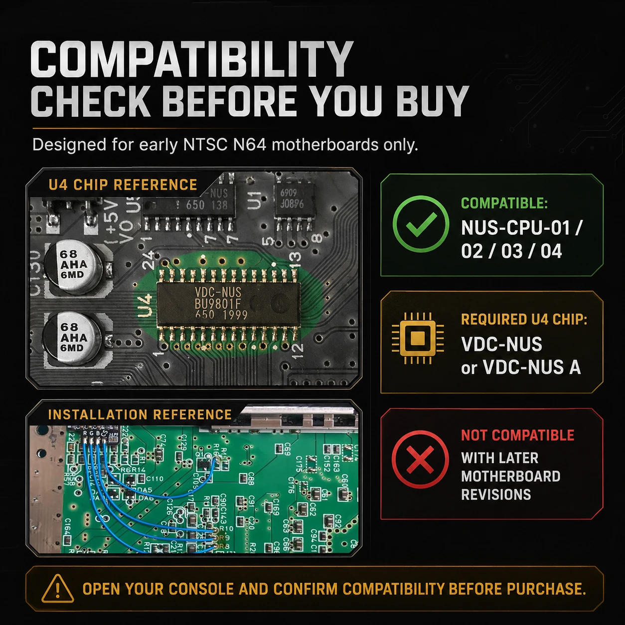
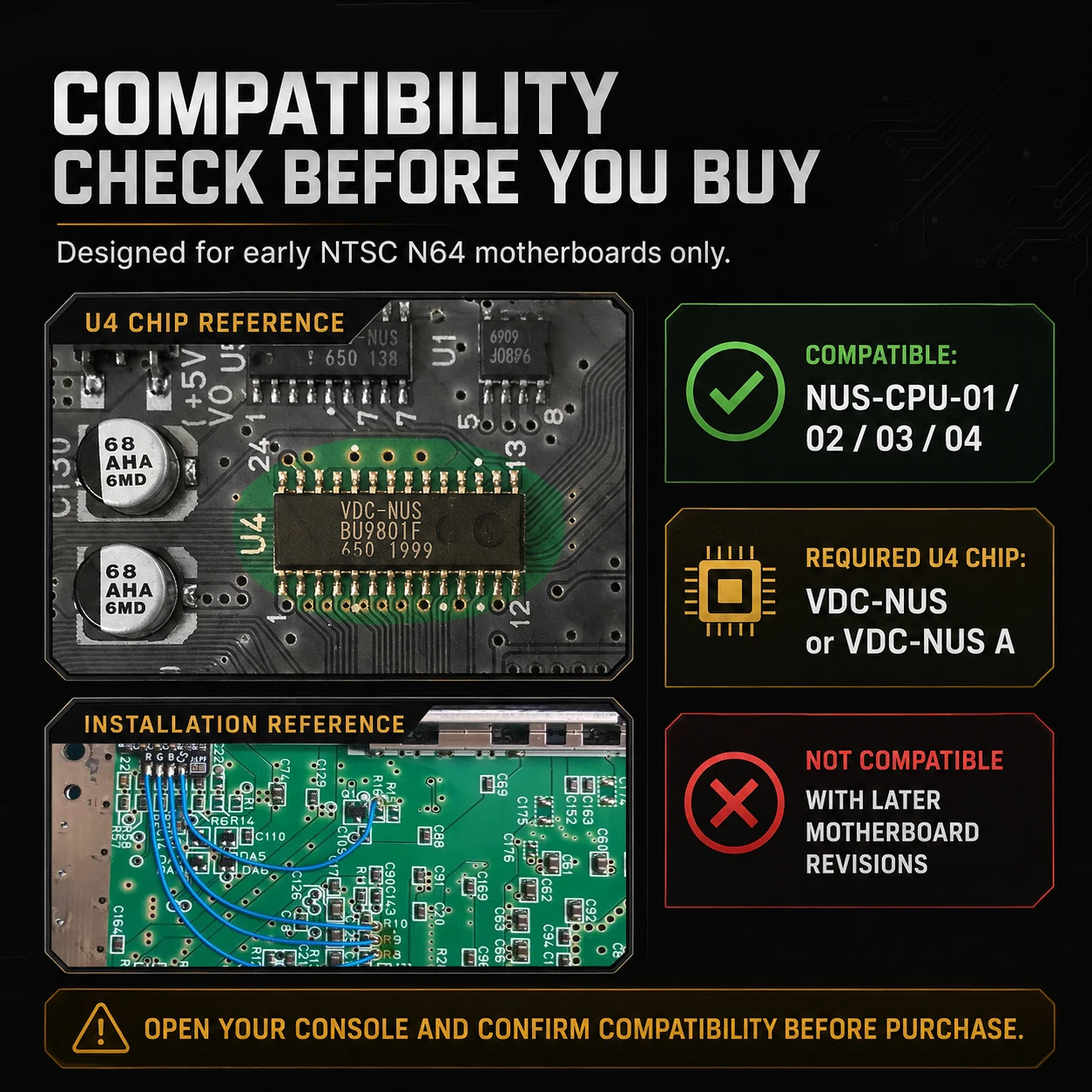
This N64 RGB Amp MOD is designed for compatible early NTSC Nintendo 64 consoles only.
Before purchase, please confirm your motherboard revision. It supports NUS-CPU-01 / 02 / 03 / 04 only, and the U4 video chip must be marked VDC-NUS or VDC-NUS A.
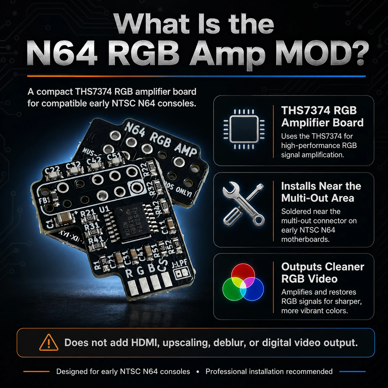
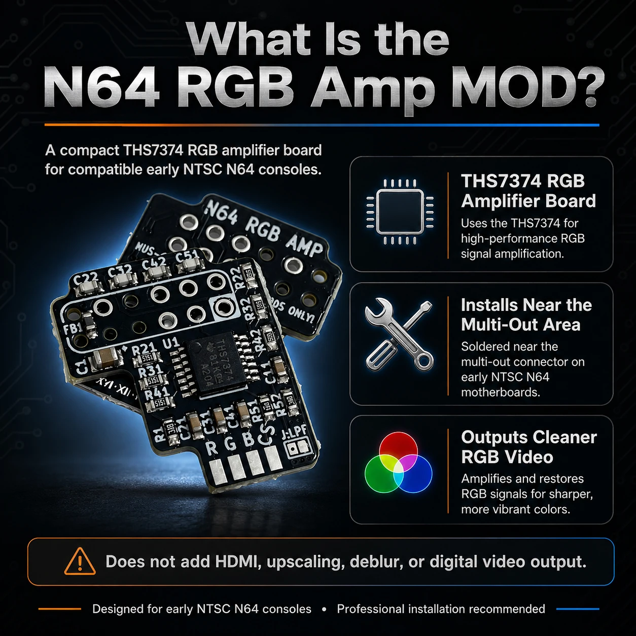
This mod enables RGB video output for a sharper and cleaner image, but it does not add HDMI, upscaling, deblur, or digital video output.
Professional soldering is required. Incorrect installation may damage the console, the mod board, or connected video equipment.
A proper RGB cable is required. RGB lines should use 220µF capacitors, and the TTL-level C-Sync line should be used with proper resistance, such as 470Ω, for most TVs, scalers, and video processors.
Please verify compatibility before installation. If your console does not match the required motherboard and U4 chip, do not install this board.
About N64 RGB Amp MOD
What is the N64 RGB Amp MOD?
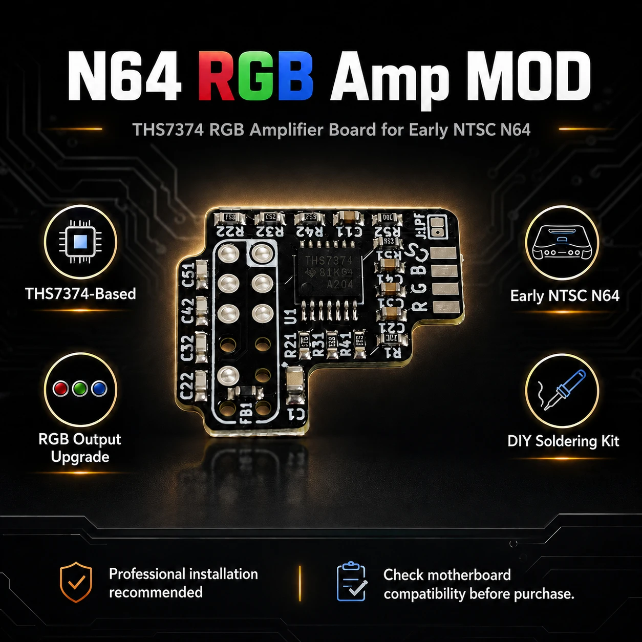
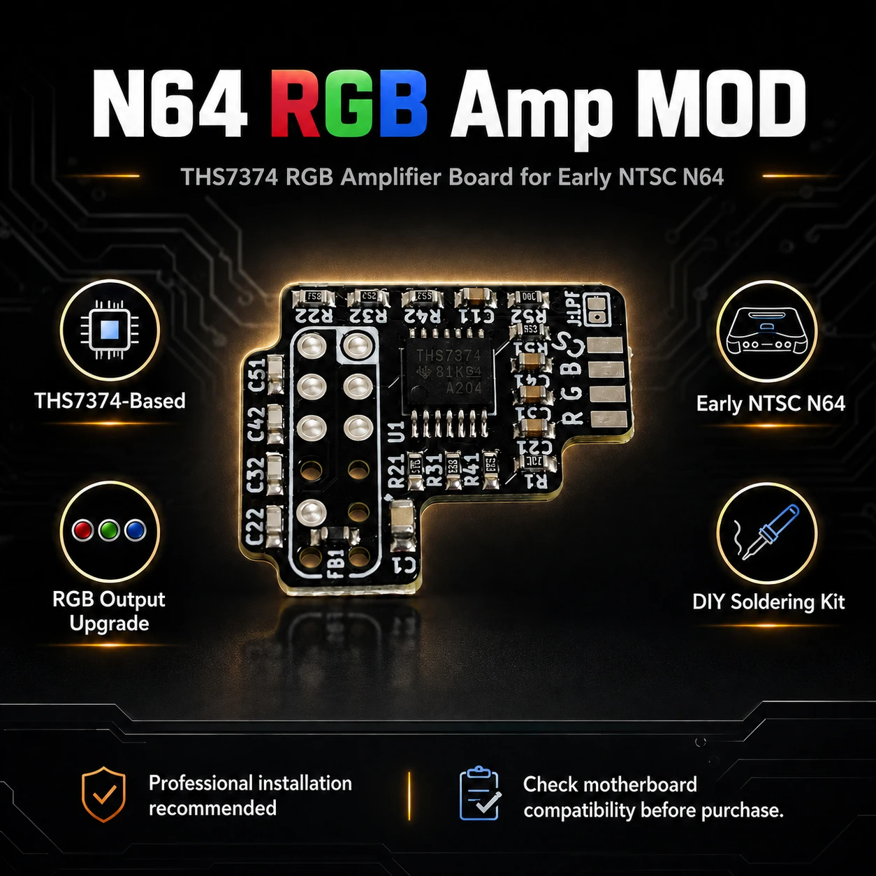
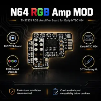
The N64 RGB Amp MOD is a THS7374-based RGB amplifier board designed for compatible early NTSC Nintendo 64 motherboards. It taps the console’s native RGB signals and outputs cleaner RGB video through the Multi-Out port.
What can it do?
It enables RGB video output for sharper image quality, cleaner colors, and better compatibility with RGB displays, upscalers, and professional video monitors. It does not add HDMI, upscaling, or deblur features.
Compatibility:
Compatible with early NTSC N64 motherboards: NUS-CPU-01 / 02 / 03 / 04 only.
U4 chip must be VDC-NUS or VDC-NUS A.
Not compatible with later motherboard revisions.
For more Installation Guide:https://github.com/TzorriMahm/N64_RGB_Amp
N64 RGB Amp MOD Installation Guide
Before Installation
Confirm that your console has a compatible early NTSC motherboard: NUS-CPU-01, NUS-CPU-02, NUS-CPU-03, or NUS-CPU-04. The U4 video chip must be marked VDC-NUS or VDC-NUS A. If your console does not meet these requirements, do not install this board.
Step 1: Disassemble the Console
Power off the console, unplug all cables, and open the N64 shell. Remove the metal shielding and access the motherboard.
Step 2: Prepare the Motherboard
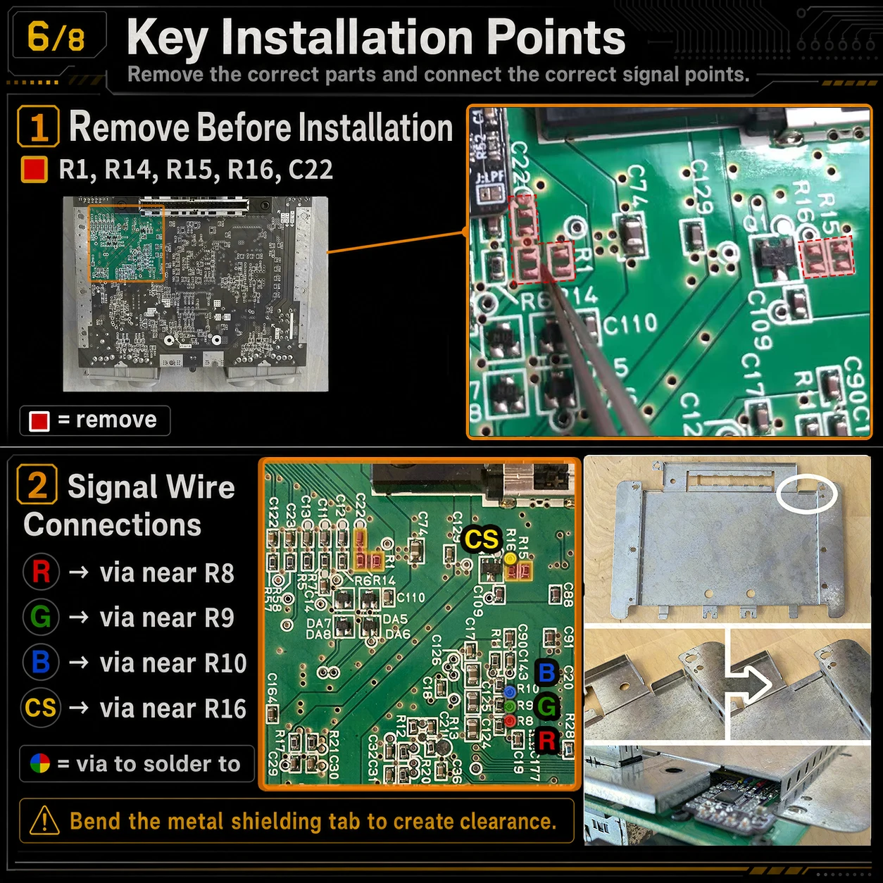
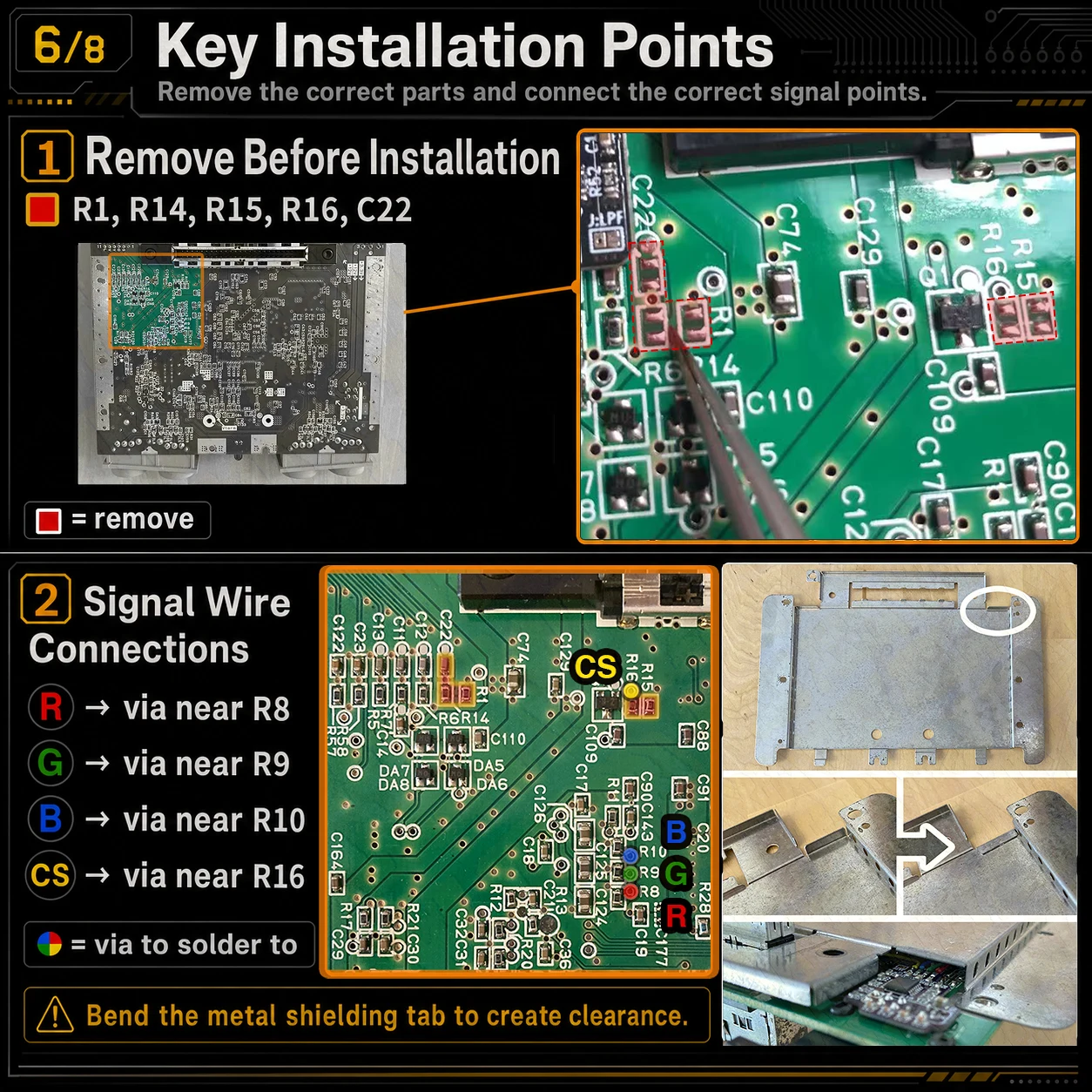
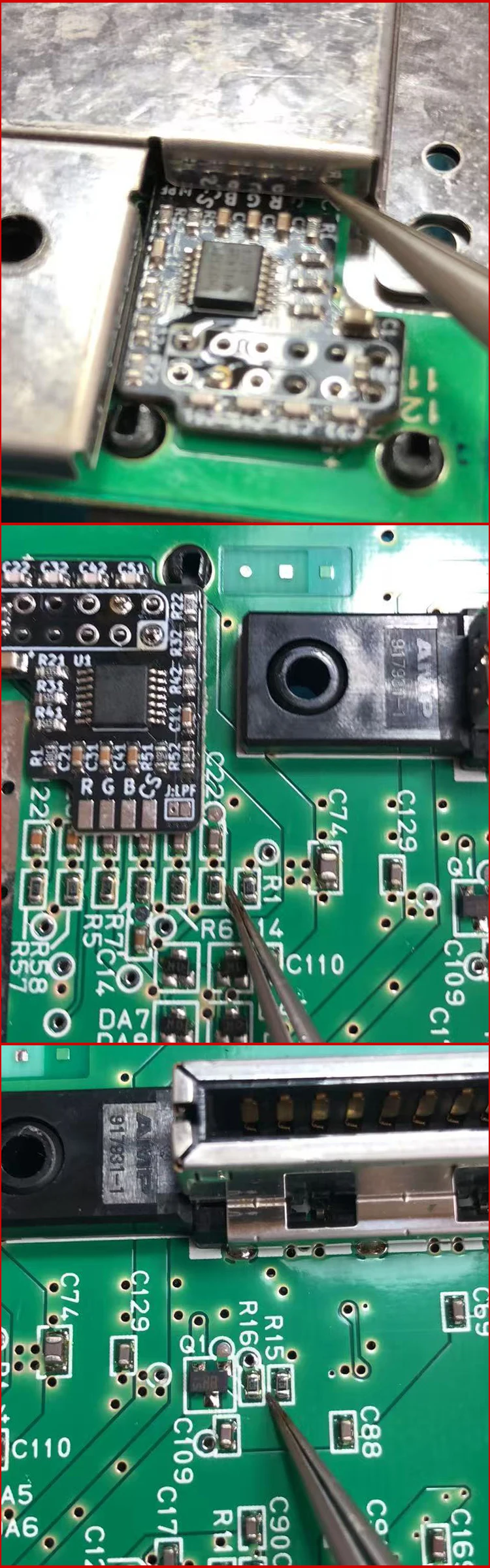
Remove the original components marked R1, R14, R15, R16, and C22 from the motherboard. Clean the pads carefully after removal.
Step 3: Prepare the Mod Board
Insulate the bottom side of the RGB mod board to prevent short circuits. Make sure no exposed pads or solder joints can touch the metal shielding or motherboard.
Step 4: Install the Mod Board
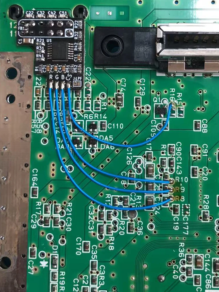
Solder the RGB mod board onto the Multi-Out port pins. Make sure the board is aligned correctly and sits flat.
Step 5: Connect RGB and Sync Wires
Solder the signal wires as follows:
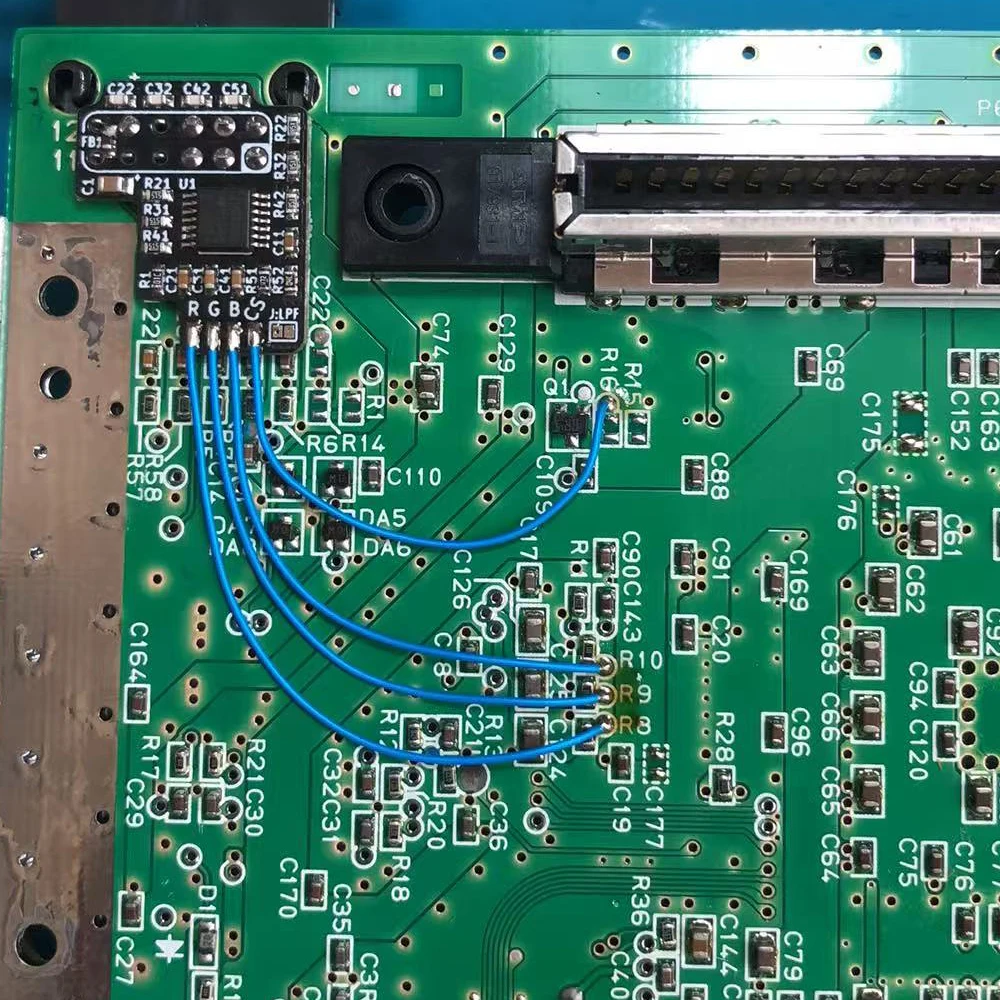
R pad on the mod board → via next to R8 on the N64 motherboard
G pad on the mod board → via next to R9 on the N64 motherboard
B pad on the mod board → via next to R10 on the N64 motherboard
CS pad on the mod board → via next to R16 on the N64 motherboard
Step 6: Check Continuity
Check each connection with a multimeter before powering on the console. Confirm that R, G, B, CS, 5V, and GND are connected correctly and that there are no shorts.
Step 7: Use the Correct RGB Cable
Use an RGB cable with 220µF capacitors on the R, G, and B lines. The positive side of each capacitor should face the console. Since this board outputs TTL-level C-Sync, a suitable sync resistor, such as 470Ω, is recommended for most TVs, scalers, and video processors.
Step 8: Optional Low-Pass Filter
The J:LPF jumper can enable the THS7374 low-pass filter. It may be useful when connecting directly to a flat-panel TV. For analog displays, OSSC, or Framemeister, it is usually better to leave the filter off and use the display or scaler’s own filtering options.
Step 9: Test the Console
Reassemble the console carefully, connect a proper RGB cable, and test the video output. If there is no image, wrong color, unstable sync, or interference, power off immediately and recheck all solder joints and continuity.
Important Note
This installation requires soldering skill and motherboard verification. Incorrect installation may damage the console, the mod board, or connected video equipment.
Advanced Image Quality Upgrade
For the best RGB performance, experienced users may also replace the aging capacitors on the N64 motherboard. This can help reduce video noise and improve signal stability.
Advanced soldering skill required. Actual results may vary depending on console condition, cable, display, and scaler.
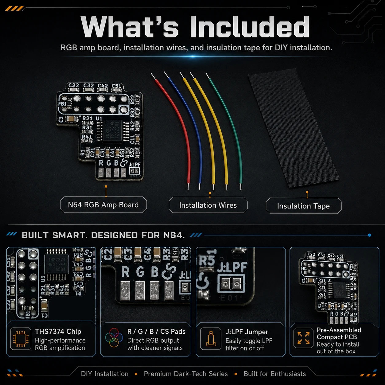
Package Includes:
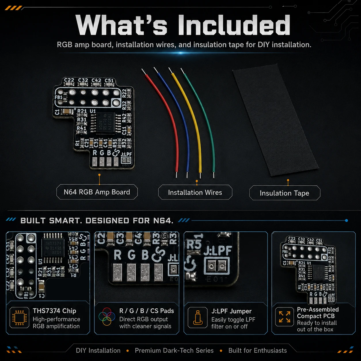
1 × N64 RGB Amp Board
4 × Installation Wires
1 × Insulation Tape
N64 RGB Amp MOD Troubleshooting Guide
1.Check Compatibility First
This RGB amp board is designed for compatible early NTSC Nintendo 64 consoles only. Before installation, confirm that the motherboard revision is NUS-CPU-01, NUS-CPU-02, NUS-CPU-03, or NUS-CPU-04. The U4 video chip must be marked VDC-NUS or VDC-NUS A. If the motherboard or U4 chip does not match these requirements, do not install this board.
2. No Power or Black Screen
If the console does not start or shows a black screen, first make sure the Jumper Pak or Expansion Pak is installed correctly. Then check for shorts around the mod board, the Multi-Out pins, the RGB signal wires, and the VDC-NUS chip. The bottom of the mod board must be insulated to prevent contact with the motherboard or metal shielding.
3. No RGB Video Output
If composite video works but RGB does not, the problem is usually related to the RGB or sync wiring. Check that the wires are connected to the correct points: R to the via near R8, G to the via near R9, B to the via near R10, and CS to the via near R16. Use a multimeter to check continuity and make sure there are no shorts between R, G, B, CS, 5V, and GND.
4. Wrong Colors or Missing Colors
If the image is too green, too red, too blue, or one color is missing, check the R, G, and B signal wires. A wrong color usually means that one RGB line is open, swapped, or poorly soldered. Also test with another known-good RGB cable, as cable faults can cause missing or incorrect colors.
5. No Sync, Rolling Image, or Scaler Not Locking
Sync issues are often caused by an incorrect cable or wrong sync configuration. This mod board outputs TTL-level C-Sync, so the sync line should be used with proper resistance, such as a 470Ω resistor, for most TVs, scalers, and video processors. Make sure your cable is wired for the correct sync type and is suitable for an RGB-modded NTSC N64.
6. Image Too Bright, Washed Out, or Over-Saturated
If the picture looks too bright, pale, or overexposed, check the RGB cable. The R, G, and B lines should have 220µF electrolytic capacitors, with the positive side facing the console. Incorrect or duplicated capacitors, missing resistors, or an unsuitable RGB cable can cause brightness and color problems.
7. Ghosting, Noise, Interference, or Poor Scaler Compatibility
Keep all RGB and sync wires short and clean. Avoid routing the wires across noisy areas of the motherboard. Make sure the mod board is properly insulated and not touching the metal shielding. If needed, test the J:LPF jumper. The low-pass filter may help when connecting directly to a flat-panel TV, but it is usually not needed when using analog displays, OSSC, or Framemeister.
8. Problems After Reassembly
If the console works before reassembly but fails after the metal shielding or shell is installed, check whether the shielding is pressing on the mod board or pinching the wires. Bend the shielding tab near the Multi-Out area if necessary, and make sure all exposed solder joints are protected with insulating tape.
9. Do Not Connect Raw RGB Directly
Do not connect the N64’s raw RGB signals directly to the Multi-Out port without a proper amplifier or buffer circuit. Raw RGB output may appear to work on some displays, but it can cause unstable video or damage the console or connected equipment.
Recommended Troubleshooting Order
First, test the console with composite video to confirm that the console itself still works. Then check motherboard compatibility, inspect all solder joints, verify continuity with a multimeter, confirm there are no shorts, test with a known-good RGB cable, and finally check sync and capacitor/resistor configuration.
Important Note
Most installation problems are caused by incorrect compatibility checks, poor soldering, wrong RGB or C-Sync wiring, unsuitable RGB cables, missing 220µF capacitors, missing sync resistance, or shorts caused during reassembly.
Reviews
There are no reviews yet.